http://www.woodiesaircraftfactory.co.uk> Wings
Wing Kit Arrived Wednesday 20th December 2017
The Wing Kit arrived at 9am and the rest of the day was spent checking off the inventory and inspecting parts for damage.
The Wing Kit arrived at 9am and the rest of the day was spent checking off the inventory and inspecting parts for damage.
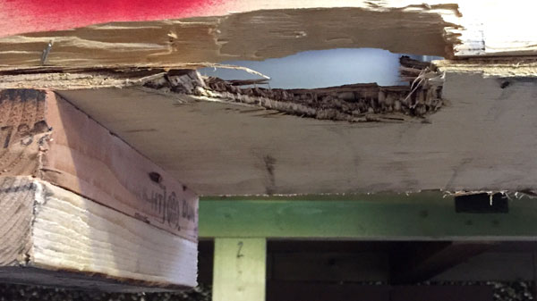
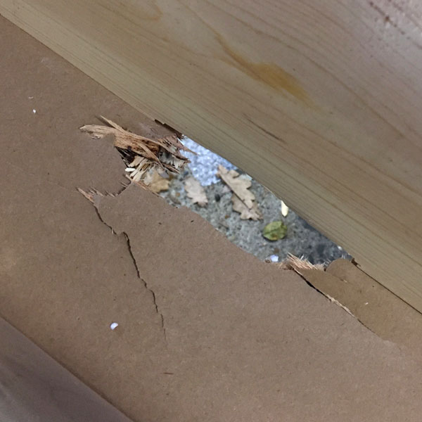
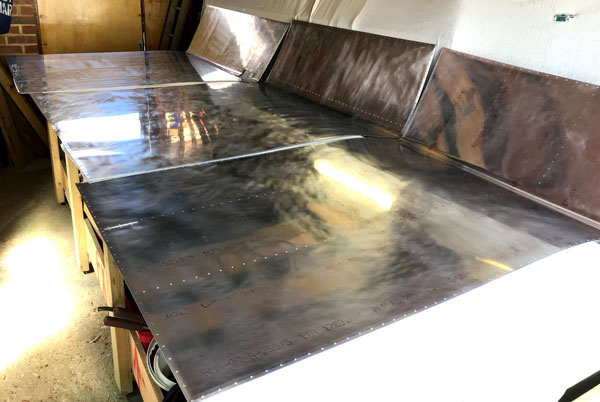
The first thing we noticed before unpacking the box was that it had been damaged by a careless forklift truck driver. We carefully inspected the wing spars in the area of the damage to the crate for witness marks that might show signs of contact with the fork, but there was no sign of this.
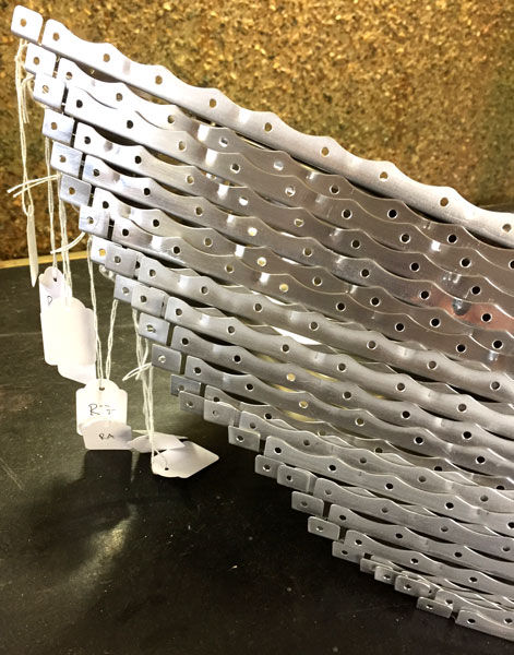
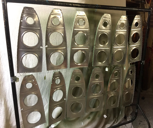
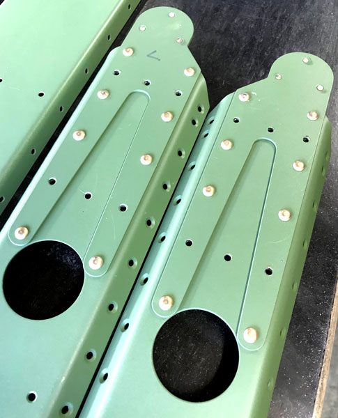
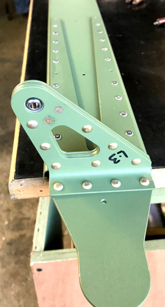
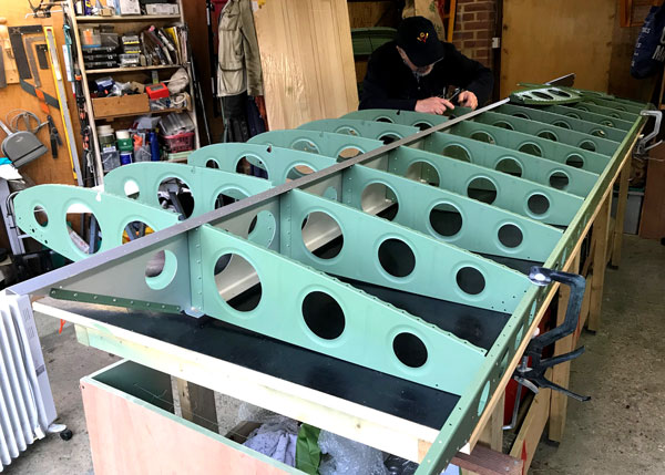
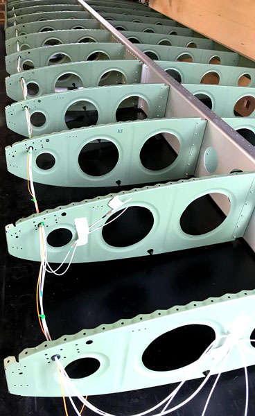
One task to get absolutely right is to correctly identify and label each rib. L and R in the part number do not mean that the rib belongs to the left or right wing, but refer to the diretion that the flange has been folded to. Then some ribs have the front flange removed, and it is only after the flange trimming is done that the rib aquires it's unique label. We labeled them R1 to R13/14 for the right wing, starting at the outboard position as per the plans, and L1 to L13/14 (there is one more nose rib to beef up the wing walk area) for the left wing, ignoring the original part number, as the original part number is not helpful after the ribs have been modified. It all makes sense when you realise that because the spars cross over in the centre of the fuselage when the wings are fitted, they are offset from the centreline of the wing chord by the thickness of the spar, and the ribs for the left and right wings have to be slightly longer or shorter to accomodate this. We did some deburring using a scotchbrite wheel on a bench grinder, but still had to do a lot of the detailed work with our micro files. The rib flanges were removed with very small cutting discs attached to a Dremel. It took some time to work out which ribs had to be dimpled and where. This always makes much more sense if you read all the relevant pages in the Kit Assembly Instructions (KAI) with the purpose of working out why a particular operation has to be carried out. Once you have worked out why, the detail of what, and which way round, becomes a lot clearer, and mistakes are less likely. The spar doublers, rib doublers and Flaperon Attach brackets also had to be match drilled and machine countersunk.The last operation, done after finishing off the deburring with red scotchbrite pads, was to flute the ribs with fluting pliers to ensure they are straight.
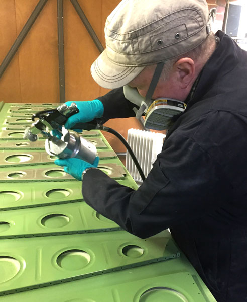
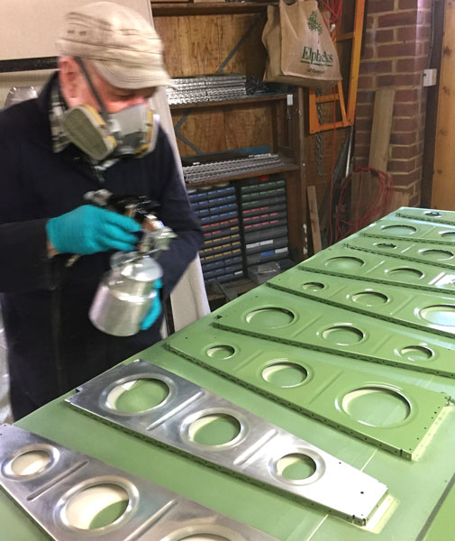
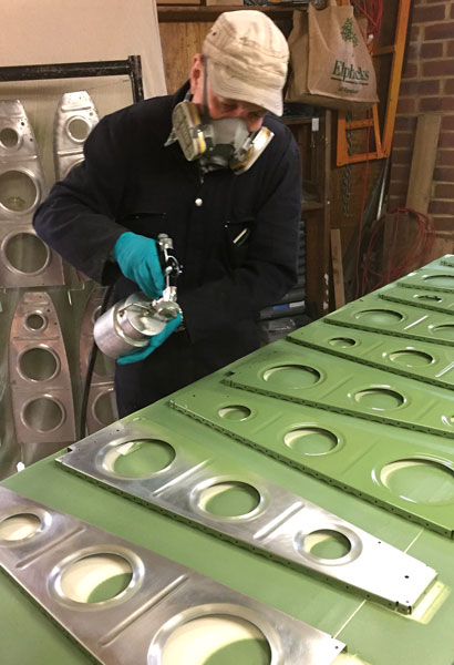
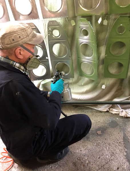
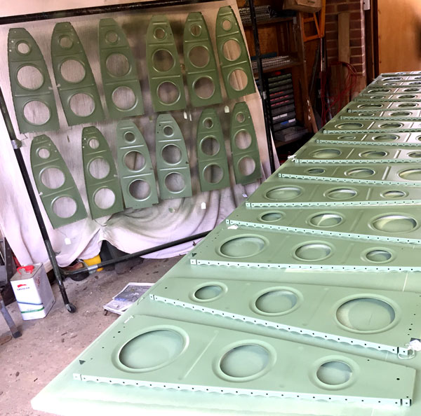
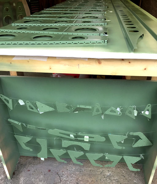
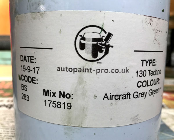
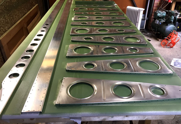
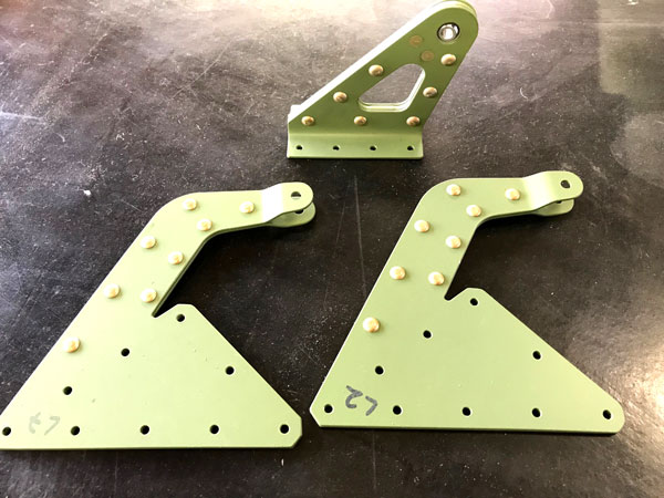
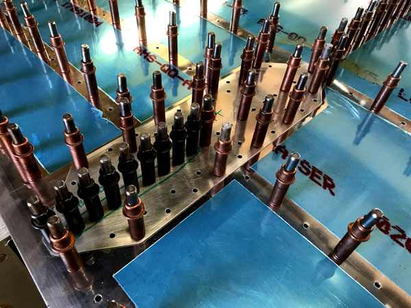
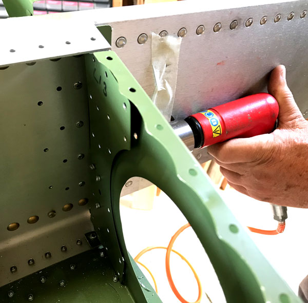
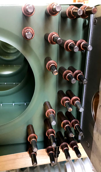
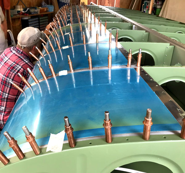
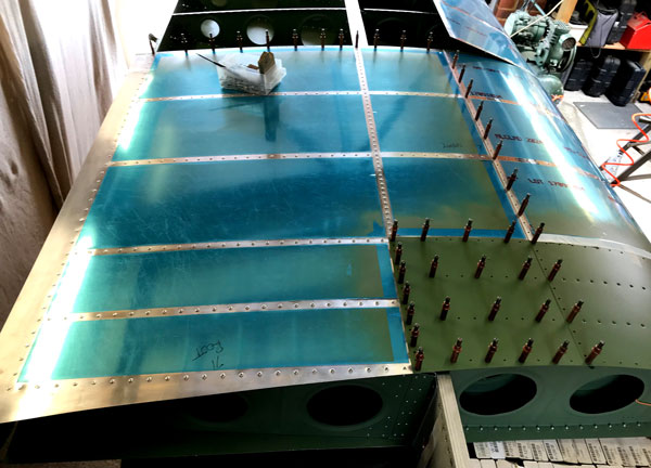
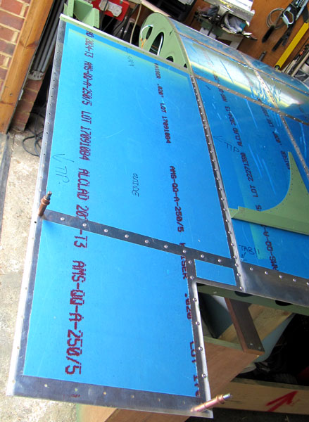
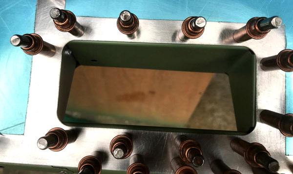
Notice at this stage we were using tie on labels for identification. We had issues with the spray gun blowing the labels on to the wet paint, so we moved to writing the ID on the parts in felt tip. As most parts had to be sprayed one side at a time, it was easy to transfer the ID from on side to the other once the first side had dried. Getting the dilution with thinners right is important to control runs in the paint. Mostly we used 50mls thinners per 100mls paint, but this could vary dependent on the ambient temperature. Also, you do not want to get too close with the spray gun, but we were tight for space, and the photos show a smaller spray gun to sprayed part distance than is really optimal for avoiding runs. The closer you are, the faster your spray strokes have to be.
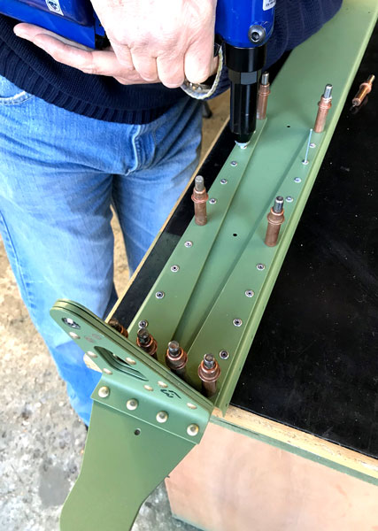
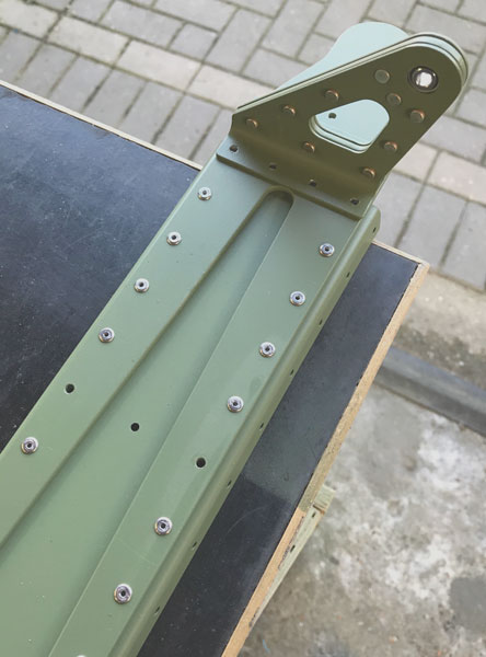
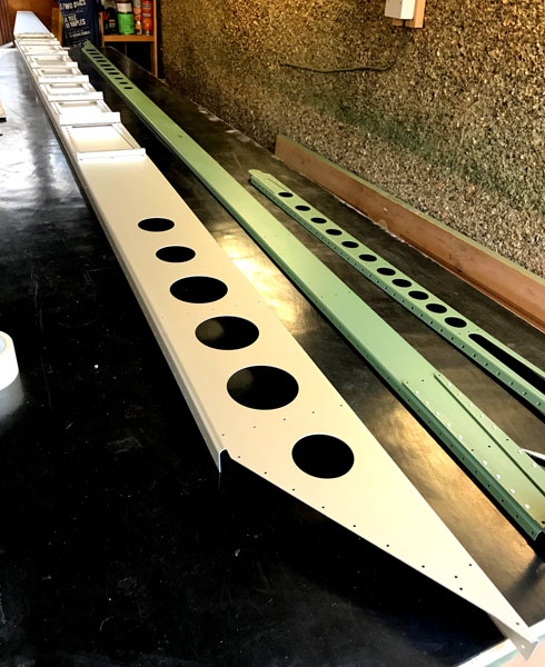
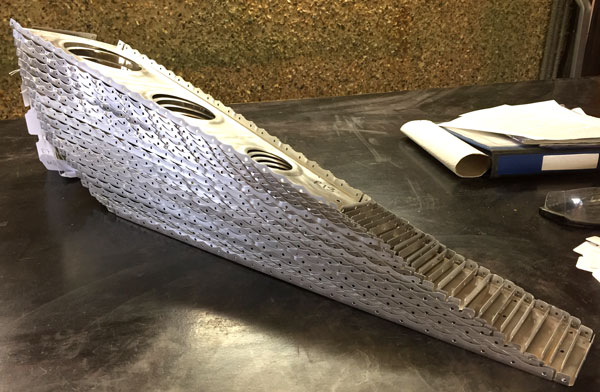
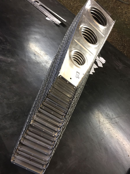
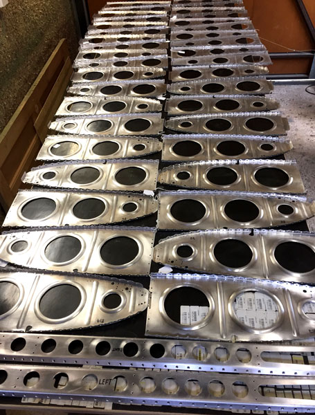
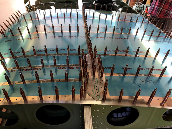
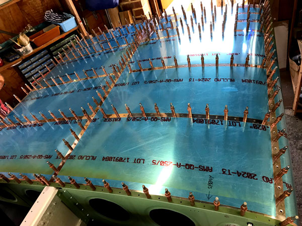
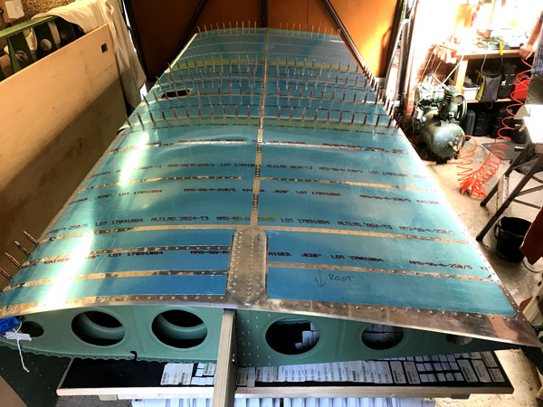
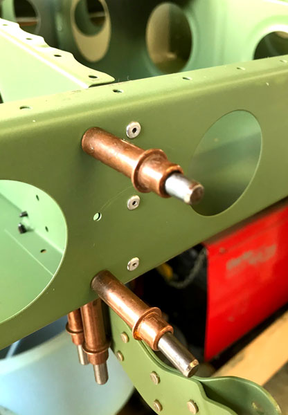
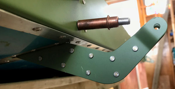
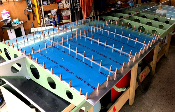
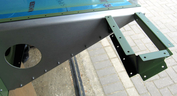
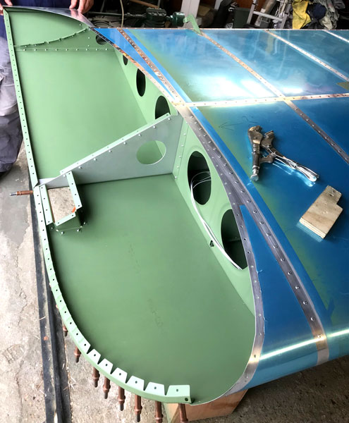
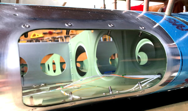
After the Sub Spar and Rear Spar had had their doublers, Flaperon Hinge and Brackets riveted on, the Main Spar was put on the bench and the attach angles already riveted on at the factory were deburred to our own exacting standards, masked out and primed with a rattle can. The AEX tie down extrusions were final drilled and tapped 3/8-16, and the remaining attach angles and rib doublers were riveted on. Then the Rear Ribs were riveted on ensuring the correct rivets (LP4-3, or LP4-4) were used, and the rivets were inserted the correct way round. Double check this because it is very easy to get it wrong. We are, of course perfect, and have absolutely no experience with drilling rivets out.
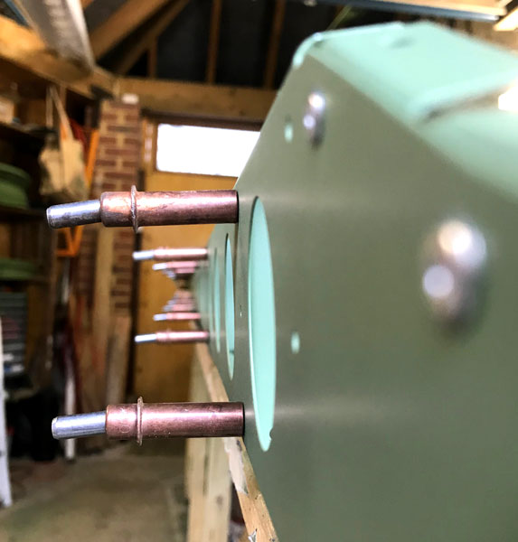
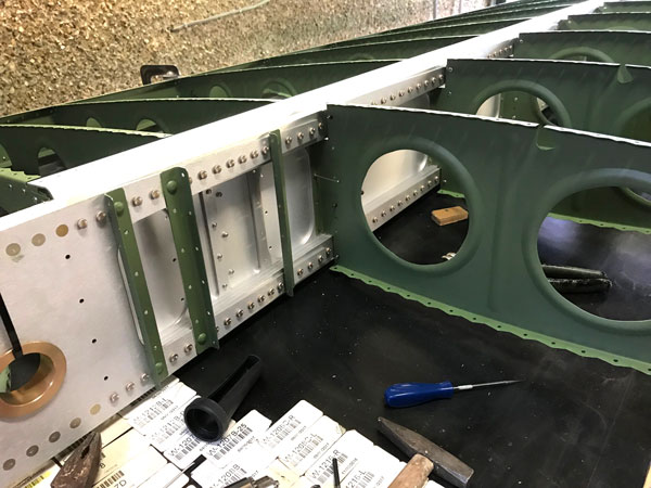

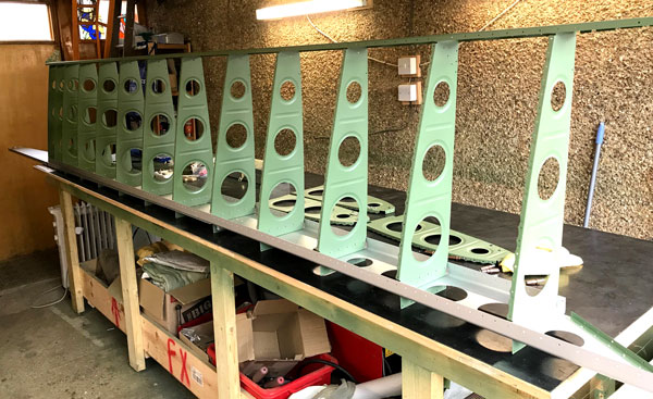
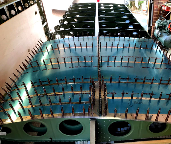
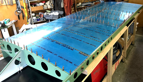
Pretty quick to construct the main wing structure. Most of the riveting on of the ribs had to make use of a little aluminium wedge with a #40 hole drilled in the centre of it so the rivets could be pulled successfully even though there was no way to get the riveter lined up straight, because it is too close to the rib. In a couple of instances, the angle was a bit too much and the rivet mandrel broke off with a very sharp stump sticking out a millimetre or so. In these cases we cut the mandrel off level with the rivet and smoothed down with the aid of a small cutting disk and small rotary grinder on a Dremel. Where there was absolutely no room to get the air riveter in, a hand puller was utilised, also using the wedge. Our Stanley hand riveter has a rotatable head so very handy for getting in tight spots.
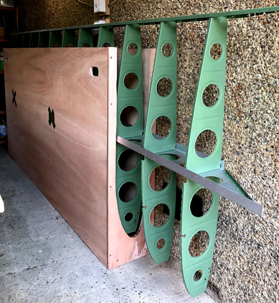
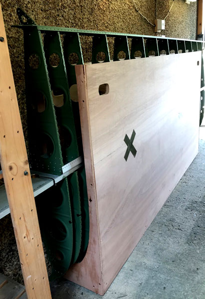
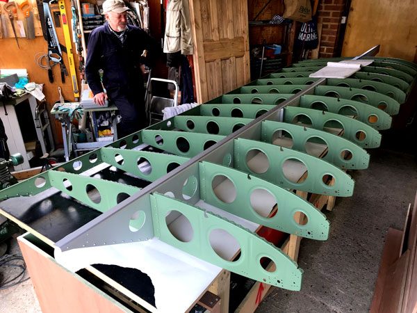
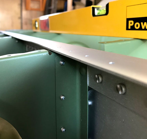
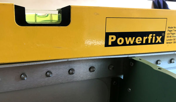
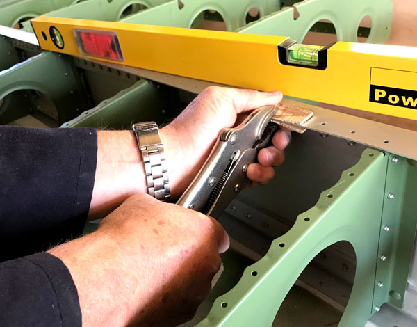
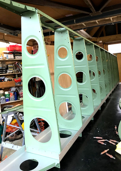
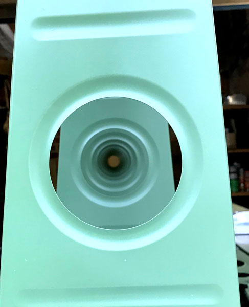
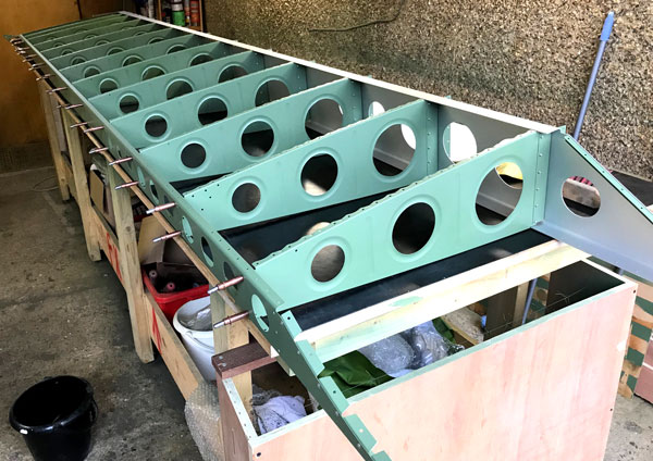
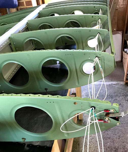
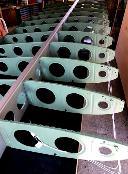
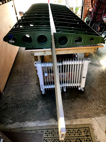
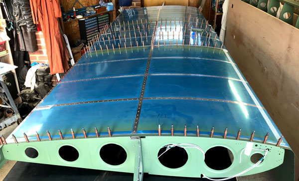
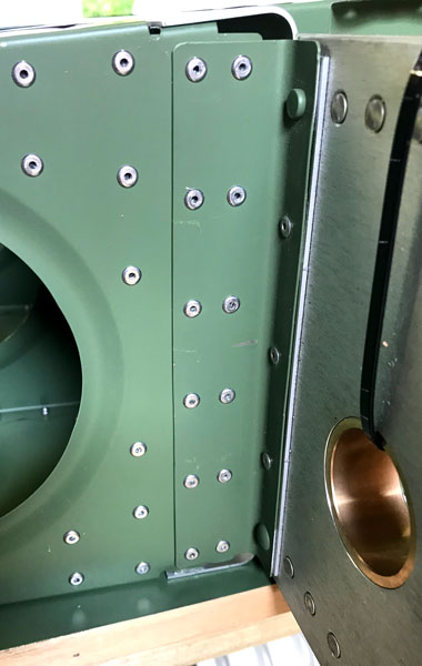
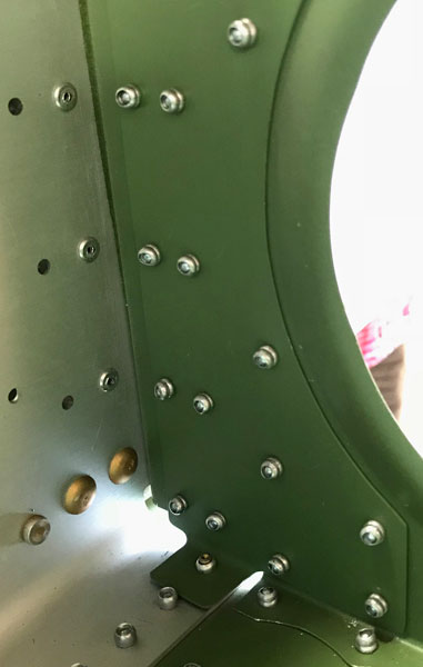
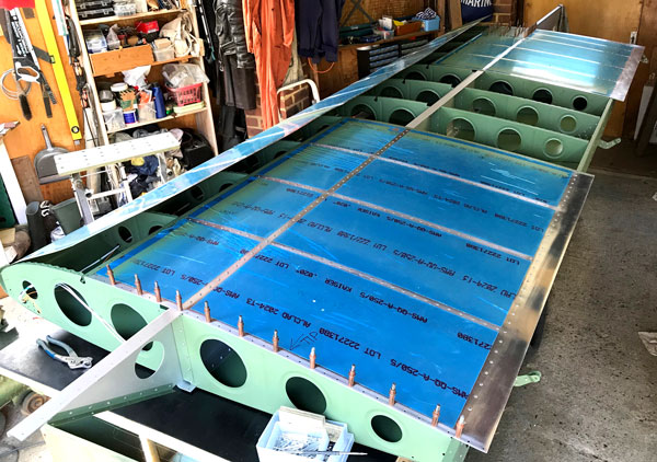
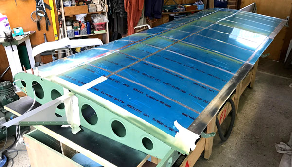
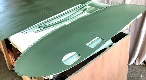
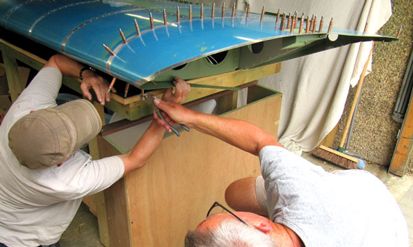
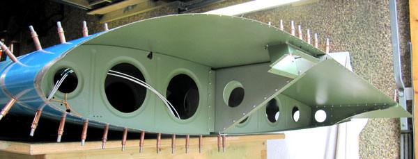
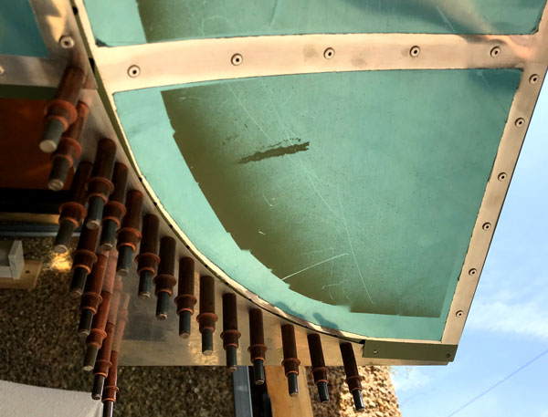
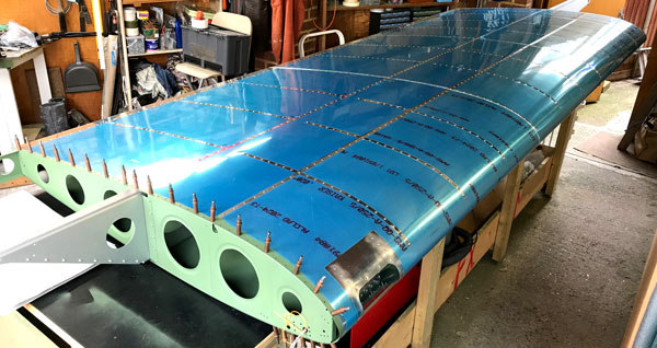
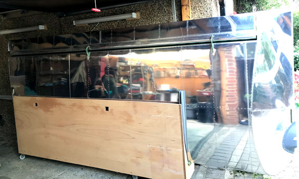
We made cradles from 5 8x4 sheets 18mm plywood and scrap battening timber to hold the wing structures upright on their leading edges against the wall. Cross pieces were inserted in holes marked by gaffer tape crosses in the pictures to support the structures on the main spars. These cradles were modified as time progressed to hold the completed wings, and castor wheels were added at a later date so the wings could be easily wheeled in and out of the garage. Our inspector called to sign off the structures before we riveted the skins on, and noticed something that we had not seen. Remember the damaged crate, pictures at the top of the page? Although there were no witness marks, it was obvious by sighting along the spar that the careless forklift truck driver who punctured the crate with a fork had also lifted the crate via the spar and put a bend in it. Our inspector was of the opinion that the bend was insignificant in terms of compromising spar strength, or affecting flight characteristics, but if we didn't straighten it, it would show up as a bad ripple in the skins. We straightend it!
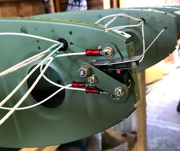
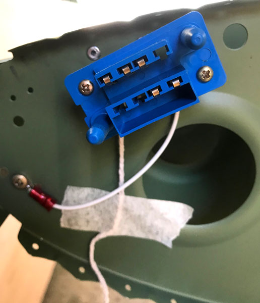
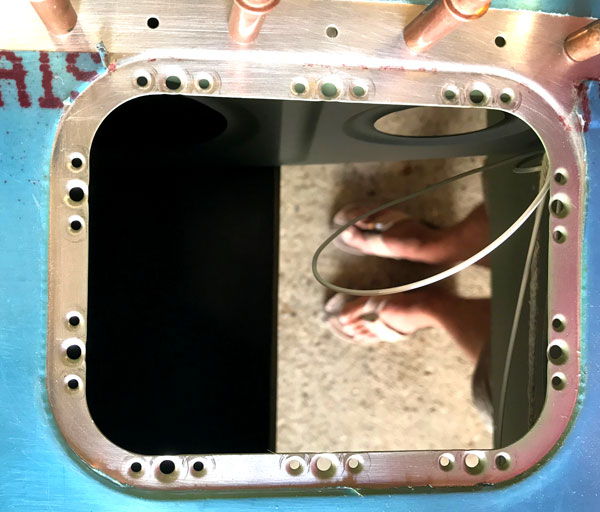
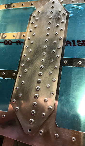
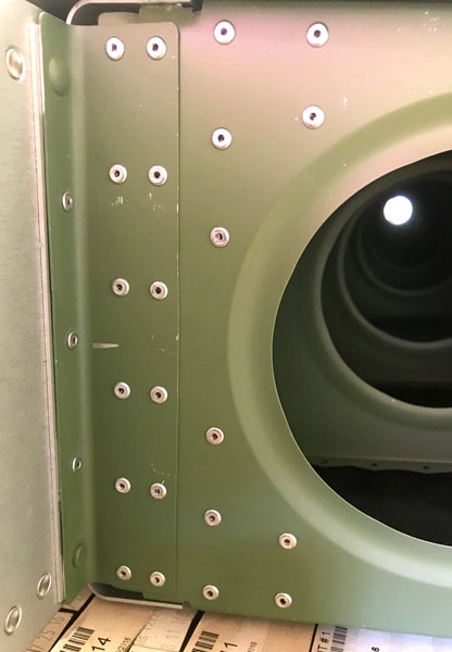
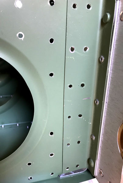
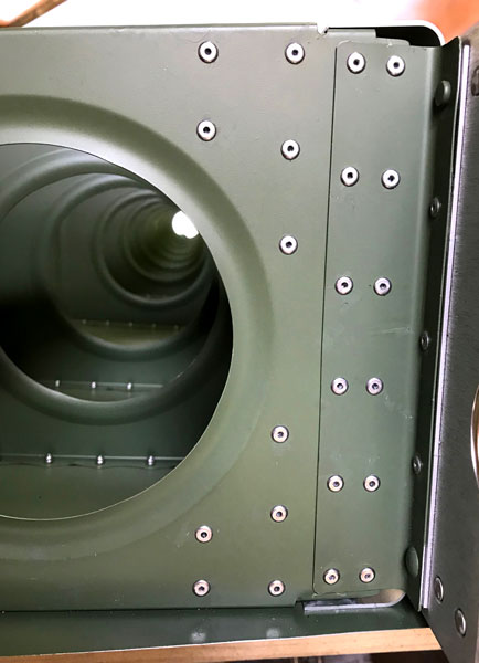
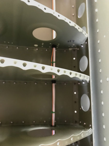
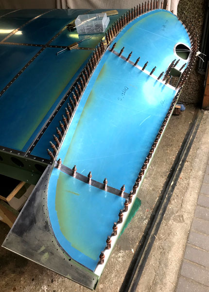
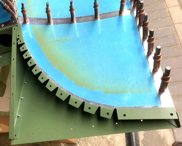
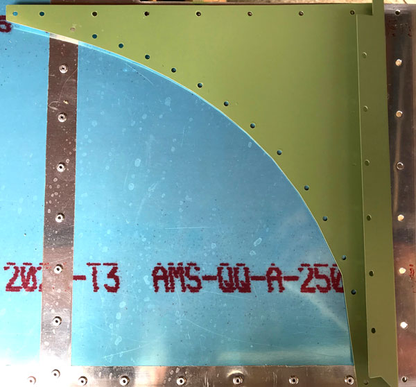
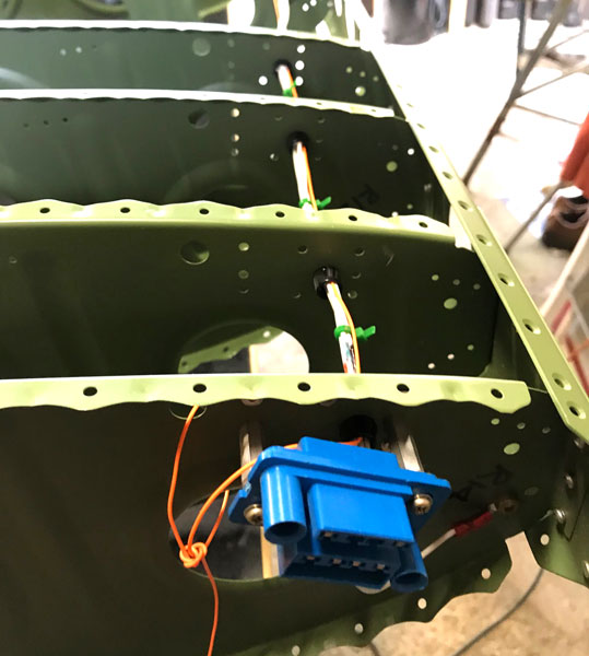
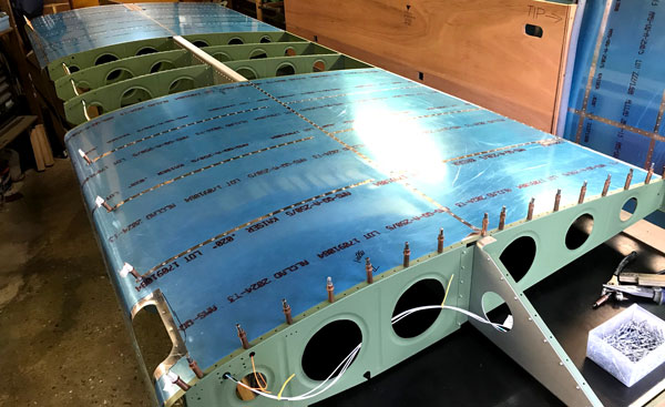
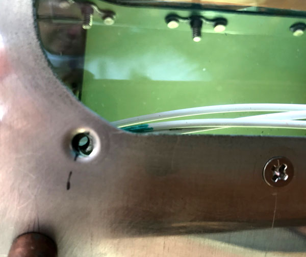
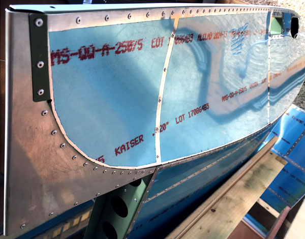
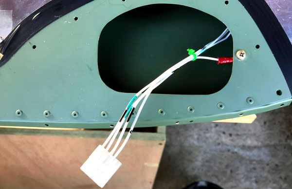
We swapped the wings around again and started to fit and wire up the stall warner and wing root connector to the left hand wing. We couldn't find the stall warner wire, so used some of the lighting kit wiring, because there looked to be more than we needed. When we came to fit the light wires, discovered that there would have been just enough. A more thorough search turned up the stall warner wire, but this meant that we had two short pieces, rather than the required one long piece, so had to order some more wire from LAS Aerospace. Once we had the connector wired up, we tempoarily connected up a 12 volt battery, and the lights, using small alligator clips and probes, and tested the connections to make sure that they worked, and that they were connected to the correct terminals. The wing skins were then deburred and primed on the inside, and overlapped edges, after cutting out the hole for the landing light with a dremel. The inboard bottom wing skin for the left hand wing was then clecoed in place along with the trapezoidal doubler so that the holes in the doubler could be final drilled. Despite noting the instruction not to final drill the most inboard hole in the doubler, we got carried away and drilled it anyway. Note to self.. Make sure to cover up holes to be left alone with masking tape before picking up the drill or riveter!!! This meant that we had to purchase some 5/32 Cherrymax rivets, as Cherrymax rivets have to be fitted to close tolerance holes. The bit in the manual about protecting the main spar with a strip of steel while drilling the holes really only applies when the doubler is being retro-fitted to an already built aircraft, the positioning determined by the pre-drilled holes making this protection unneccessary for the later builds, at least, as far as we could figure.
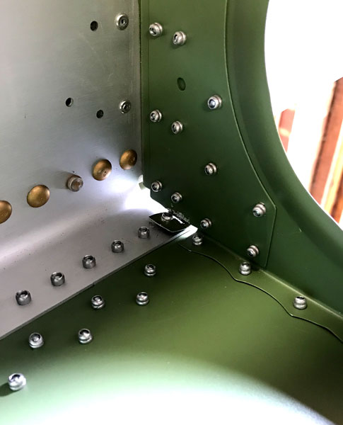
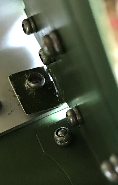
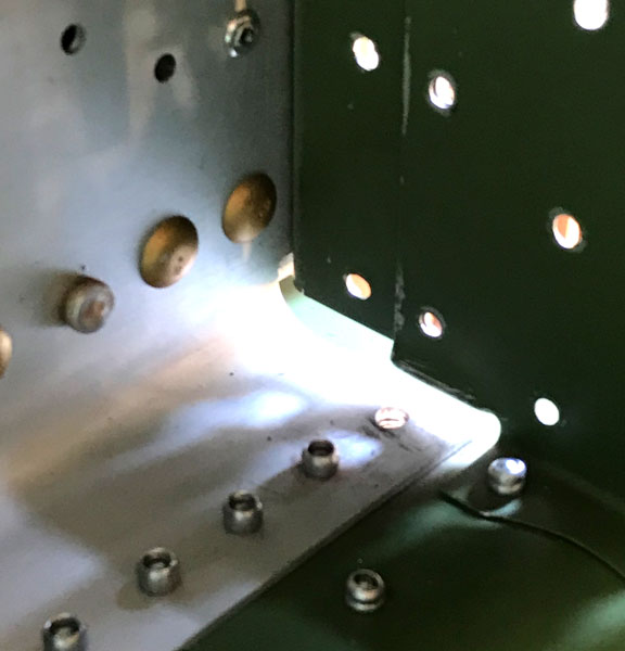
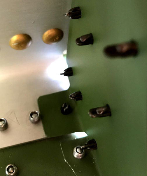
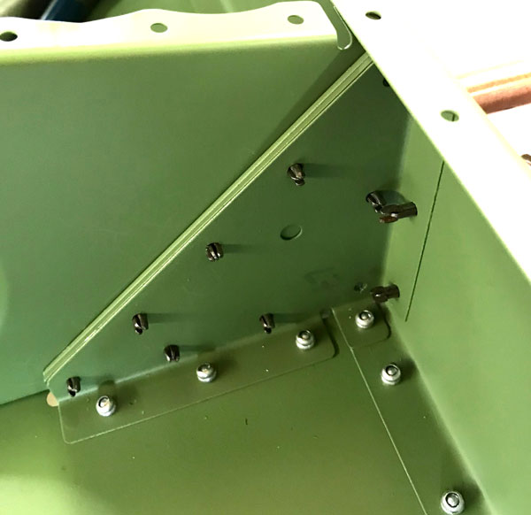
We compounded the error in drilling the doubler hole oversize by being so keen to fit the oversize 5/32 Cherrymax rivet when it arrived, we forgot to check that it did not bend the tab on the rib when we pushed it through. The result was that the rivet went only part way through the tab, so worst case scenario. While drilling the rivet out released it from the doubler and wing skin, we could not remove it from the tab because it had expanded on both sides of the tab hole, and in our efforts to wiggle it free we ended up breaking the tab off.
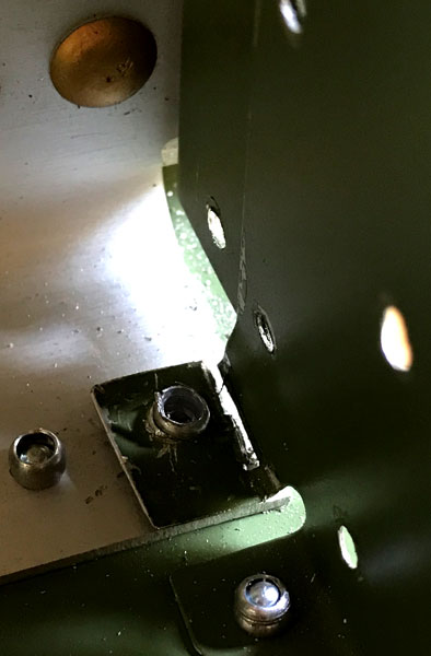
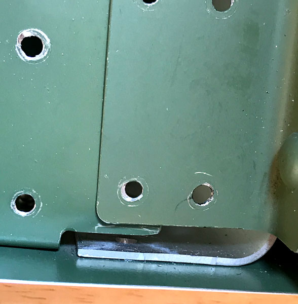
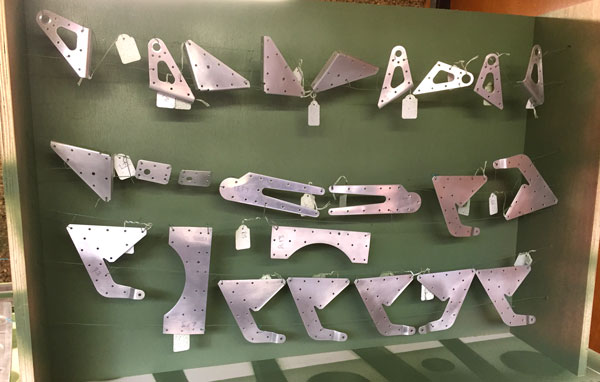
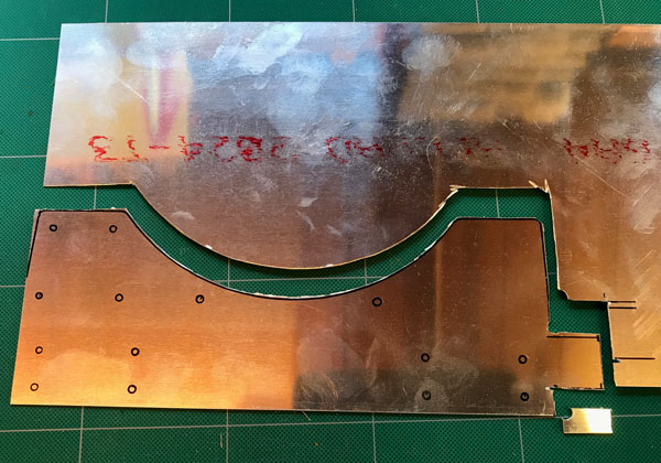
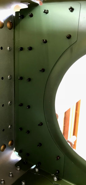
Our inspector paid us a visit, and said he would be happy if we just deburred the rib, and replaced the tab with a separate piece with a right angle bend, riveted to the spar and the rib/doubler. We thought it would be a much better repair if we re-made the doubler and made the tab on that, instead of the rib, and our inpector said that if we were prepared to go to that degree of effort, he would be very happy. We could, of course, have ordered a new rib from Vans, and drilled out all the rivets holding the old one in, and done a complete replacement, but this came with the risk of elongating holes during the rivet removal process and causing more problems. Plus, of course, we would have to twiddle our thumbs while waiting for the new rib to arrive. We had enough of the correct thickness aluminium sheet, we had a dremmel. What was the problem!
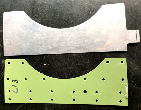
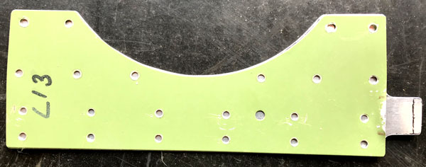
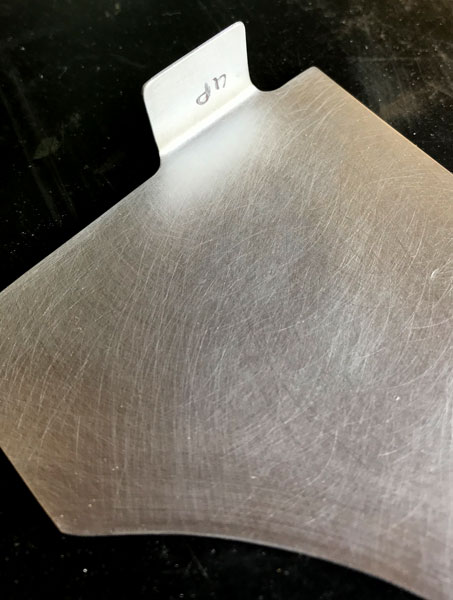
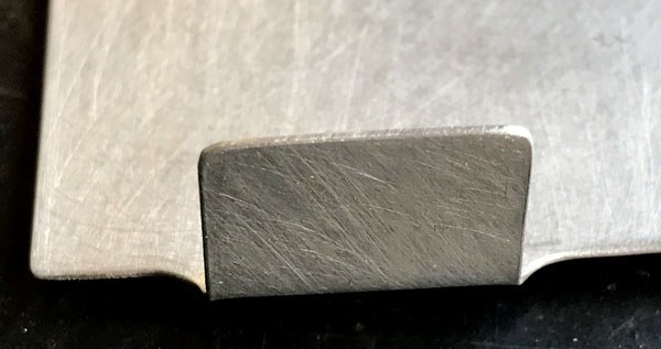
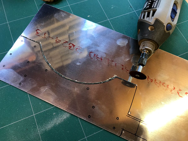
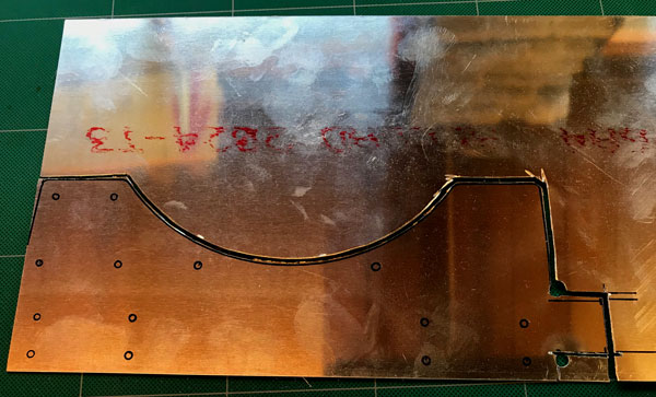
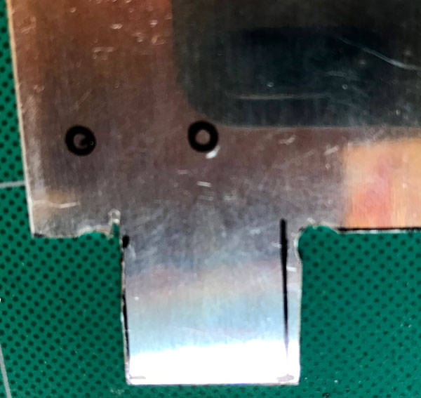
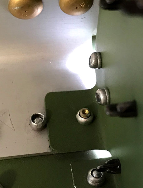
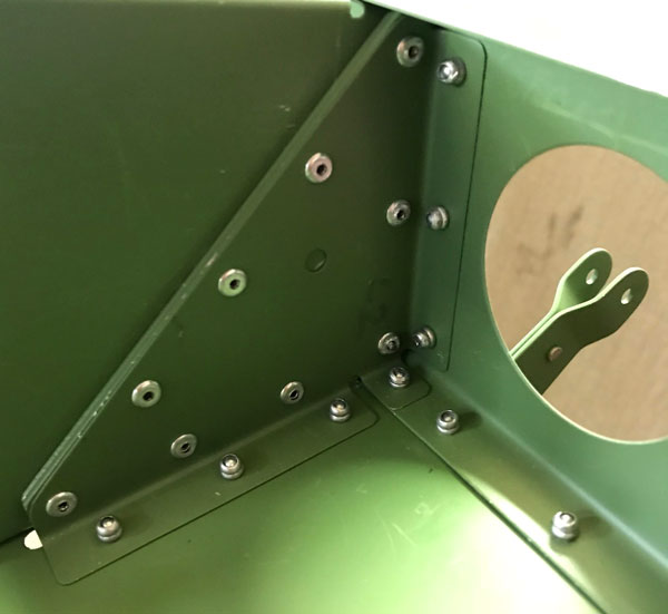
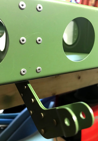
For the first attempt, we put the bend in the tab, and then used the old doubler as a template to drill the holes. This turnred out to be a bad idea, as getting the correct relationship betwwen the position of the bend and the overall hole positions is difficult (impossible) to do using this method. Subsequent attempts showed us that the correct sequence was to put the bend in as close as we could get it to the correct place...more than one attempt required. Then clamp in position and mark and drill the hole in the tab. Then clecoe and clamp, and match drill to the holes in the rib and attach angle, clecoeing as drilling proceeded. It took the manufacture of 3 decorative aluminium objects, and one actual useful part to get there. We learned a lot.
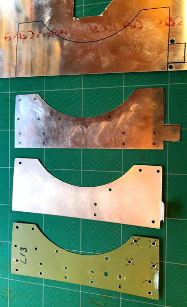
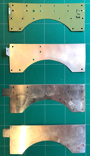
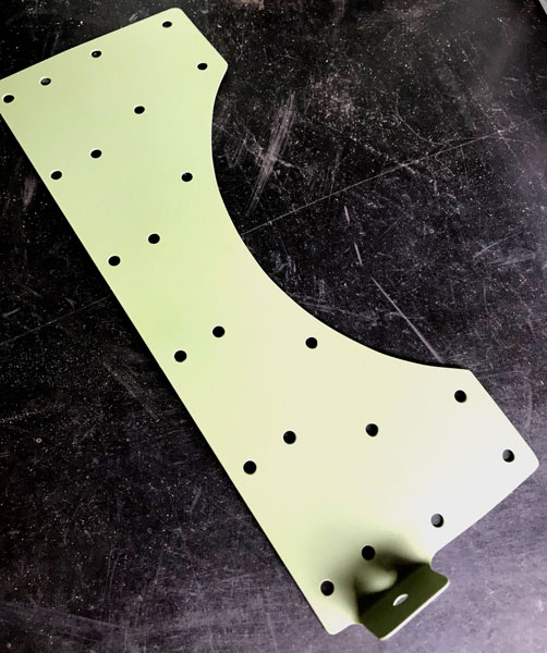
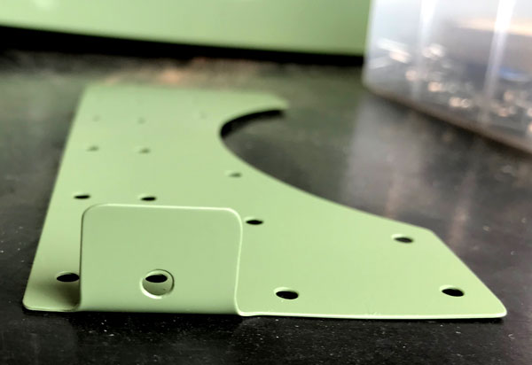
Our experience with the first prototype showed us that we would probably need more than one further attempt to get it right, so we made the decision to make two more blanks while we were at it. The exact fit we achieved with the final finished piece was very satisfying.
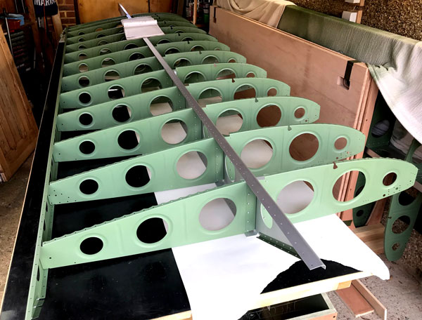
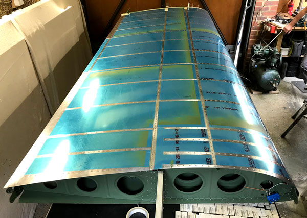
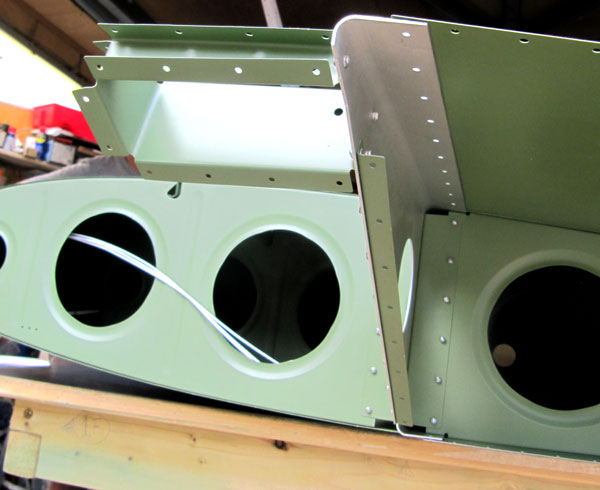
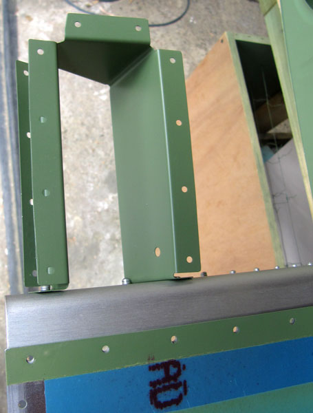
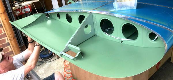
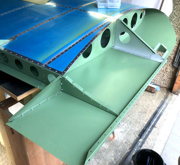
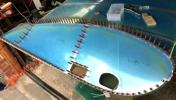
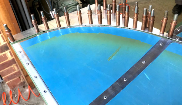
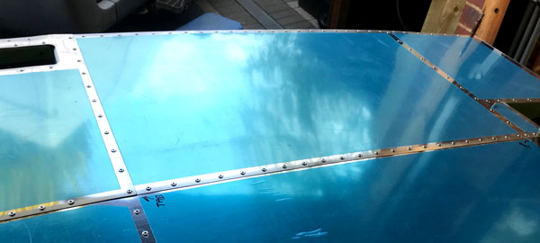
The next job, after the broken tab affair, was to rivet the bottom middle wing skin on, followed by the Flaperon hinge brackets and rib doublers. Because it was difficult to find room for even the hand riveter, which had to be held at an angle, a wedge was needed. To get the wedge positioned properly, it was modified with a slot, rather than a hole. This worked for most of the rivets, except that on one rivet, the rivet mandrel broke off with a sharp bit sticking out of the rivet by 1/4". This was dressed smooth with a dremel. Note that it was much easier to rivet on the rib doubler gussets first, otherwise the hinge bracket makes it impossible to get a riveter onto the doubler rivets. The photos illustrate the sequence for the Flaperon bracket and doubler gusset to be riveted on. This is done exactly the same for two positions. The second rib in from the inboard end, and the seventh rib in from the inboard end.
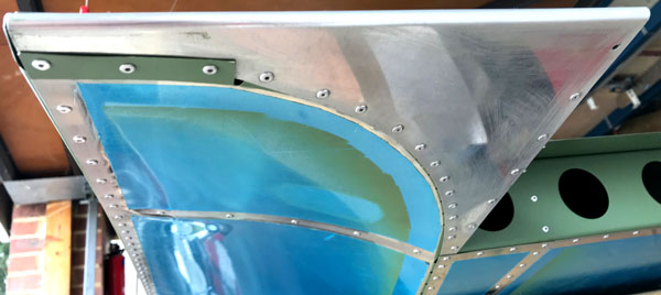
The final task was to construct the wing tips, starting with the frame that makes up the wing tip hand hold. The most satisfying bit was the appreciation of the curve of the bottom wing tip skin when finally riveted in place. The least satisfying bit was the fact that there was a very definite "oil canning" effect on the top wing tip skin after the rivets had been set. It is possible to reduce this somewhat by taking care with the riveting, which we did for the other wing, but our inspector advised us that it was of no real consequence, and not worth taking the risk of drilling the rivets out to try and improve it. Examination of a variety of RV12s at Sywell one year showed us that most of them have oil canning in this area to a greater or lesser extent.
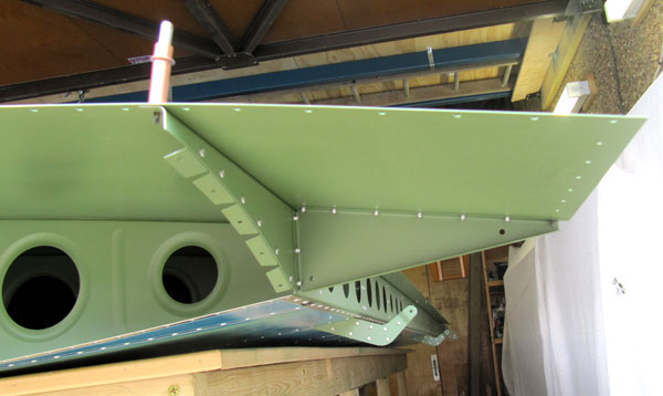
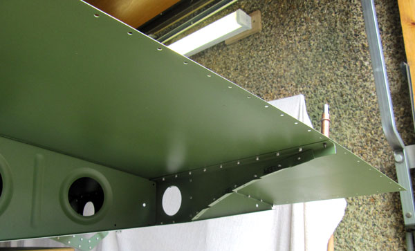

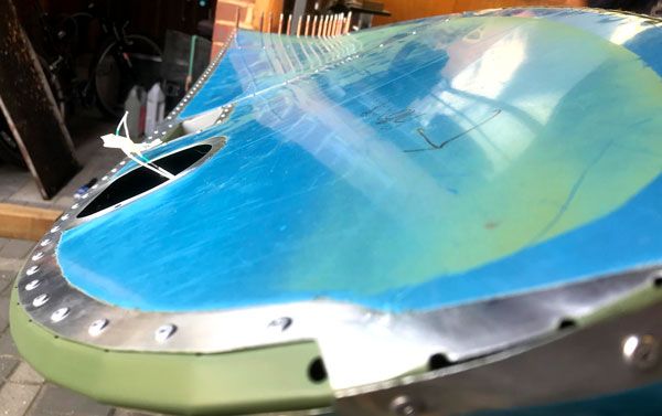
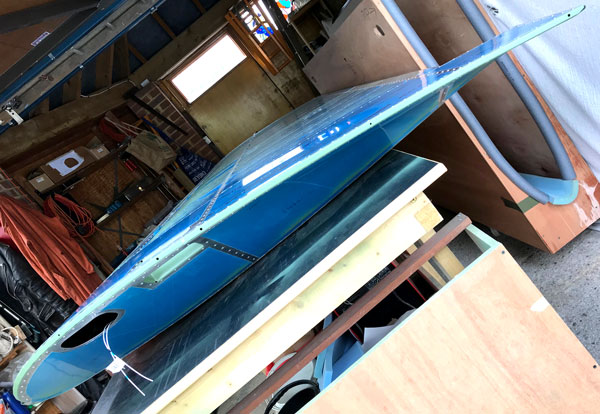
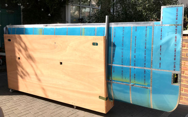
We fitted the wing tip trailing edge close out so that there were no edges running counter to the airflow. This means that we overlapped the last tab on the curved wing tip bottom skin over the top of the wing tip close out piece. We then used three rivets, not two, to hold it down, so we had to drill an extra rivet hole mid-way between the two existing holes. The finished wing was stored in the same cradle the spar and rib structure was stored in, but modified by using plastic guttering to rest the leading edge in and lining the cradle ends with tubular foam insulation, and adding castor wheels. These cradles will be modified further to make getting the wings in and out of them easier, then discarded altogether for a much better design, details later.
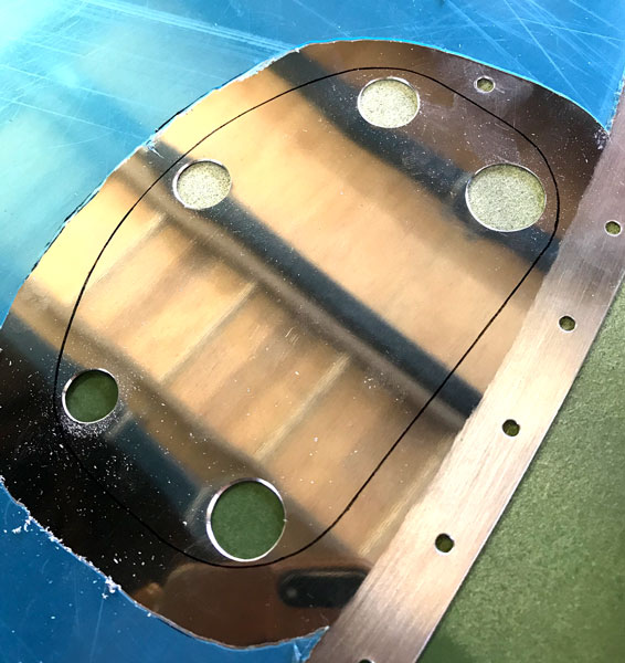
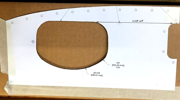
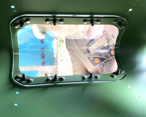
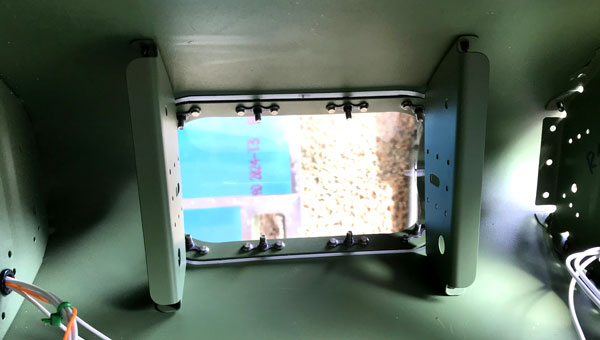
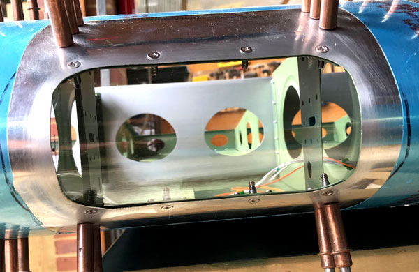
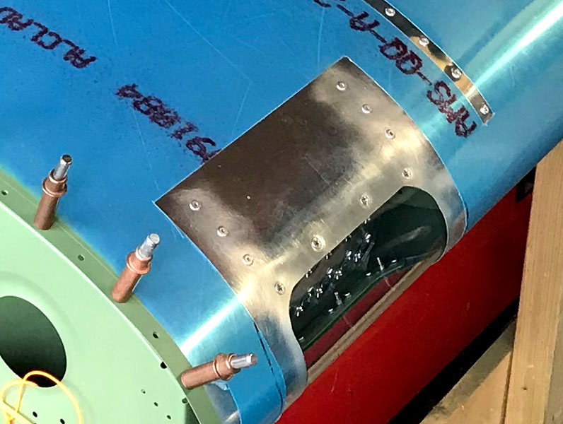
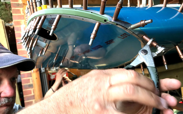
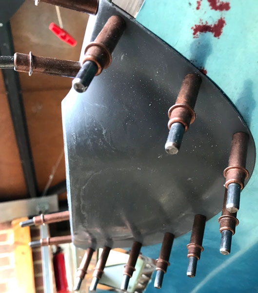
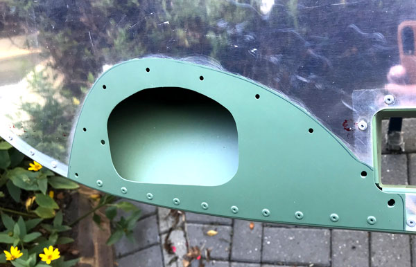
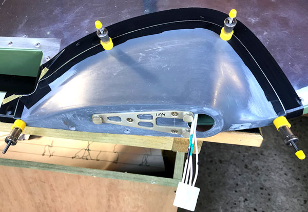
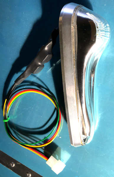
The process for completing the right wing is exactly the same as for the left, but went easier and faster because we knew what we were doing, and we double checked that we did not bend any tabs when placing the rivets. While the left wing is wired for the stall warner and nav light, the right wing is wired for a landing light and nav light, so the big difference is that we had to cut the hole for the landing light, using a dremel and cutting disc, as well as the hole for the nav light fitting. We also had to trim and drill the perspex cover for the landing light.
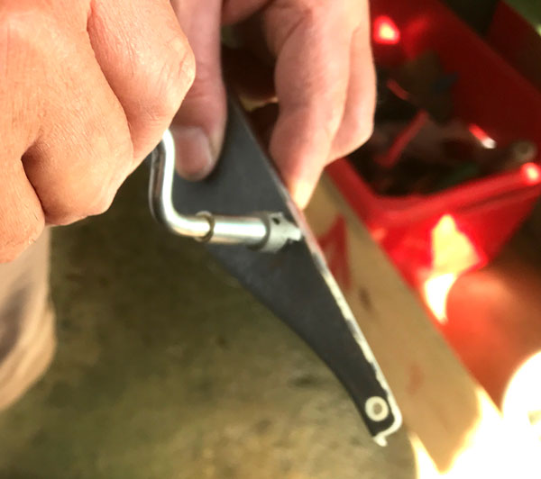
The landing light perspex was trimmed to size with a very fine toothed hacksaw, sawing slowly by hand. #30 Holes were drilled and dimpled in the wing skin. The perspex was held in place by wedging it tightly with a piece of wood against the wing spar, the perspex being protected by a small rolled up towel, and #30 holes were drilled with a standard drill bit, but using a hand drill slowly with light pressure. Final size of the perspex was achieved by sanding with 80 grit and finishing the edges with 120 grit sandpaper. The #30 holes were opened out to 4mm, as we did not have a #27 bit, and 4mm is very slightly larger that #27. They were then countersunk by using the countersink head in the hand de-burrer. The wedge arrangement must have shifted when we did the last hole, because it was not completely lined up. This was fettled by flattening out the dimple and elongating the hole with a file, then re-dimpling to the filed side. The hole in the perspex was also filed slightly oblong and countersink adjusted with a file. All adjustments did not show beyond the scew head when fitted.
The flaperon brackets and wing tip assembly was exactly the same as for the left wing, except we took special care to flute the Wing Tip rib and ease the rivet holes and ensure the top wingtip skin sat flat with no tension before setting the rivets. This reduced the oil canning effect considerably.
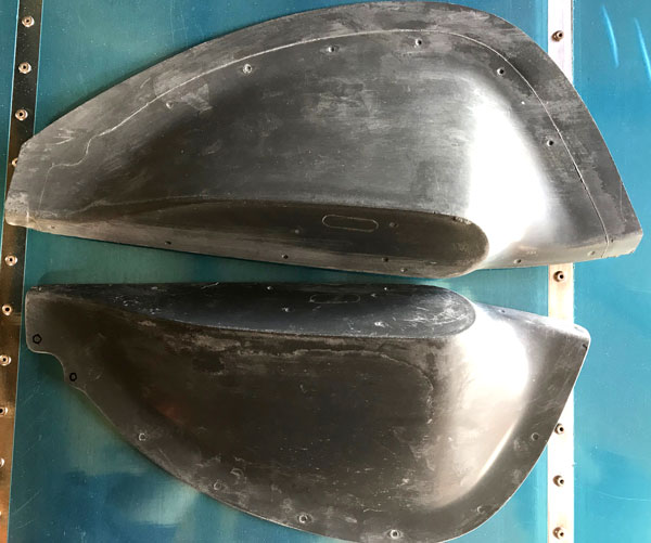
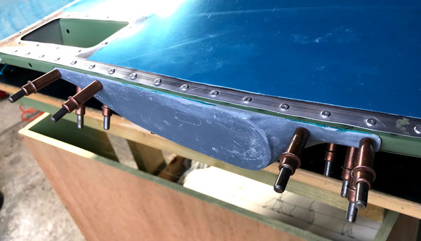
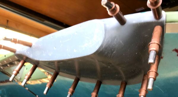
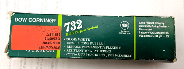
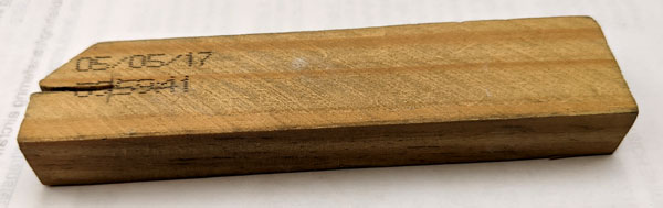
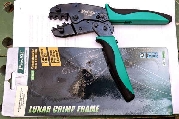
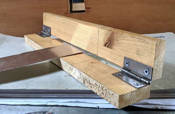
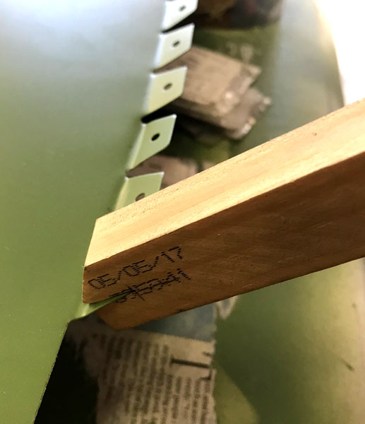
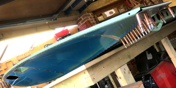
A dremel was used to trim the Nav Light fairings to shape. 3 Rivets had to be drilled out from each wing, so if you are going to fit Nav Lights, look up these rivets and don't set them in the first place. The KAI expects you to have to drill them out. The trimed fairings were match drilled and clecoed on as drilling progressed, then a line was traced around to mark out where the wing skin would need priming underneath the fairing. West System Mini 101 repair pack was used to build up the edge of the fairings using cling film as a release agent. We went for the smallest resin pack we could find because it would be some time before we would need to do the next round of epoxying. We also obtained a 120 degree countersink from Cleveland Aircraft Tools in the States, required for countersunk pop rivets, and used it on the end of a hand de-burring tool to make the countersinks in the fiberglass fairings. Because the fiberglass is relatively soft, the air driven pop riveter is a bit heavy handed. A more controlled rivet pull can be achieved with the hand riveter. The rivet next to the light bracket is difficult to set even with the hand riveter and a wedge, but we managed it by finding a suitable small nut and a washer to slip over the rivet mandrel and hold the riveter out a bit so that it did not foul the bracket. Its a process called trial and error!! We slavishly followed the KAI and used insulation tape to protect surfaces, then realiseed that we did not have any fuel tank sealant anyway. A call to our inspector elicited some Dow Corning 732 silicon sealant which was used instead, with the added benifit that it was a lot less messy to use. Also pictured is the Wooden Tab Bending Tool for bending wingtip tabs made as per KAI (Kit Assembly Instructions). The Taiwanese Proskit Lunar Open Barrel crimping tool for crimping the Molex connectors was purchased from LAS Aerospace (Part No E300-005) for £33.63 ex VAT, 2018 prices, and worked well. The final task was to connect up a 12 volt car battery to the wing root wires and check that the lights actually worked. All OK. The final picture above shows the completed right wing with Flaperons fitted, although it would be some time before we completed and fitted the Flaperons.